FOR DOWNLOADING .pdf FILE PLEASE CLICK HERE.
(The .pdf file is password protected, write your email in comment box to get password.)
In a real power system, there is very rarely a situation where a perfectly symmetrical and balanced system exists.


1) Explain the
significance of symmetrical components in real time power system analysis,
apart from which they are said to be designed for analyzing unbalanced system?
Without symmetrical components,
it would be very difficult to analyze unbalanced loading, the effects of
harmonics, and fault studies.
Also the impedances of loads are dependent on the sequence networks.
For example, the positive sequence a, negative sequence and zero sequence impedance networks of a synchronous machine are all different from each other.
Also the impedances of loads are dependent on the sequence networks.
For example, the positive sequence a, negative sequence and zero sequence impedance networks of a synchronous machine are all different from each other.
In a real power system, there is very rarely a situation where a perfectly symmetrical and balanced system exists.
2) Do the sequence
networks of synchronous machines vary with the fault?
The sequence impedances of a
generator are different during fault conditions; there is the sub-transient
impedance (stage 1), transient impedance (stage 2) and synchronous impedance
(stage 3).
3) Is there any relation
between the fault and the occurrence of several sequence networks?
Any power system during a fault
can be analyzed with 3 equivalent sequence networks: positive, negative and
zero sequences. And there are 3 different equivalent circuits for each
sequence.
4) And how can the
protective equipment be able to differentiate between the different sequences
currents?
Modern numerical protection
relays calculate the sequence currents and voltages from the CT and VT inputs
just like someone would calculate it by hand.
5) What is the use of VFD and tell about its working.
We
could replace the 3-phase motor starter with Variable Frequency Drive (VFD) to
operate the fan at variable speed. Since we can operate the fan at any speed
below its maximum, we can vary airflow by controlling the motor speed instead
of the air outlet damper.
6)
What is Skin Effect?
Property
of a conductor by virtue of which a line offers different resistances at
various frequencies of AC. Thus , a dc resistance of any conductor is not
constant always , rather it is quite different from its high frequency
resistance. This occurs due to difference in flux linkage with the outer
surface and deep inside the conductor.
7) How will you find the transmission line voltage by observation?
We can
tell the Transmission line voltage by observing
·
Level of insulation used
·
Thickness of conductors
·
No. of conductors
·
No. of parallel conductors of one phase (for
400 kV it’s 2 and for 765 kV it’s 4 conductor for one phase)
All the
above factors can give us rough idea of voltage for which the line is designed.
Further, there are very few national standards which will help us reaching
close to the accurate answer.
8)
Why do we not use frequency below 50 Hz and what will happen?
Going
much below 50Hz would cause incandescent lights to flicker. The threshold for
humans to perceive such flicker is typically about 16Hz, though it can be
detected at higher frequencies by some people.
If the
frequency is increased substantially, inductive loads become very high
impedance, requiring higher voltages to drive the same amount of current.
Considering motors (which are inductive loads) use something like half the
world's electricity supply, this would be a bad thing. Also, transmitting them
across large distances becomes a problem due to the effects of inductance of
long lines. Further, higher frequencies require generators (with a given number
of poles) to rotate faster. Going too high increases wear and tear, in addition
to adding mechanical instability. The 50 to 60Hz region provides a good
compromise. Why 60Hz is used in some parts of the world (primarily USA) while
50Hz is used in others is because of historical artefacts that are not really
cost effective to remedy.
That
said higher frequencies allow the use of lighter transformers and smaller
motors and lower frequencies reduce inductive effects over long lines. Higher
frequencies (such as 400Hz) are used for specialized purposes (such as in
aircraft, where weight is important and you don't have to worry about long
lines) and lower frequencies are used in some railway traction systems.
9) Does the reverse
saturation current flow in the reverse direction of the conventional current in
a diode under reverse biased condition?
If we keep
the normal convention of voltage vD and
current iD directions in a diode, the reverse current is
negative. The usual electrical equation of the diode is
iD=IS[exp(vD/(ηVT))−1]iD=IS[exp(vD/(ηVT))−1]
Where iS, η and VT are
diode parameters.
If vD is
negative (diode with reverse voltage) then the exponential is approximately
zero and we can write
iD≈−IS
This is the negative value of current seen
in the example picture below, marked as "Reverse Current". If the
reverse voltage gets too large, then the diode enters in breakdown and usually
blows out (unless it is prepared to do it in a controlled manner, such as it
happens with Zener diodes.)

10) Why surge impedance
loading does not change with compensation?
The surge
impedance loading (SIL) of a line is the power load at which the net reactive
power is zero. So, if your transmission line wants to "absorb" reactive
power, the SIL is the amount of reactive power you would have to produce to
balance it out to zero. You can calculate it by dividing the square of the
line-to-line voltage by the line's characteristic impedance.
So
compensation is designed while taking into consideration the SIL.
Hence, with
change in compensation, the SIL will change (& vice-versa).
11) What is Surge
Impedance Loading? Derive it.
The surge impedance
loading or SIL of a transmission line is the MW loading of a transmission line
at which a natural reactive power balance occurs.
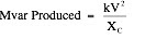
Transmission lines
produce reactive power (Mvar) due to their natural capacitance. The amount of
Mvar produced is dependent on the transmission line's capacitive reactance (XC)
and the voltage (kV) at which the line is energized. In equation form the
Mvar produced is:

Transmission lines
also utilize reactive power to support their magnetic fields. The
magnetic field strength is dependent on the magnitude of the current flow in
the line and the line's natural inductive reactance (XL). It follows then
that the amount of Mvar used by a transmission line is a function of the
current flow and inductive reactance. In equation form the Mvar used by a
transmission line is:

A transmission line's
surge impedance loading or SIL is simply the MW loading (at a unity power
factor) at which the line's Mvar usage is equal to the line's Mvar production.
In equation form we can state that the SIL occurs when:

If we take the square
root of both sides of the above equation and then substitute in the formulas
for XL (=2pfL) and XC (=1/2pfC) we arrive at:

The term  in the above
equation is by definition the "surge impedance”.
in the above
equation is by definition the "surge impedance”.
 in the above
equation is by definition the "surge impedance”.
in the above
equation is by definition the "surge impedance”.
12) Is a transformer
neutral to be grounded? When can earthed cables be used? When can the un-earthed
cables be used?
Neutral
grounding of most generators and transformers are so designed to identify and
control fault currents involving ground (i.e., L-G and L-L-G faults) as it
affects the zero-sequence current. As the question is about transformers it is
the practice nowadays to have all the EHV and UHV transformers effectively
grounded so that the line voltages of healthy phases during a L-G
fault does not exceed 80% of L-L voltage.
To assist
in the process of insulation coordination, Basic Insulation Levels (BIL) has
been recommended. Insulation of Lightning Arrestors (LAs), transformers,
switches, CBs, bus bars etc must be able to withstand a surge of this value
with a factor of safety. Thus BIL value decides the required rating of LAs, and
insulation of transformers, switches, CBs, bus bars etc, both against surge and
power frequency voltages. This BIL value depends on the status of
grounding.
For
example, a 220 kV system will have a BIL of 900 kV if system
is effectively grounded and 1050 kV if non-effectively
grounded and consequently the required insulation against surge voltages
for transformers may be 1050 kV or 1300 kV (next standard BIL values)
respectively. The insulation of switches and CBs, bus-bars are also affected in
a similar manner.
13) What are the factors
affecting Corona? What is the advantage and disadvantage of Corona?
Factors
affecting Corona:
·
Atmosphere- Corona depends on the physical condition of
atmosphere. In a rainy or stormy weather corona will be more at less voltage.
·
Space between the conductor- Spacing between the conductor is also
depend on the corona more space in between the conductor less
electrostatic effect and less corona.
·
Line voltage- Line voltage is also affect on corona, greater the
line voltage more corona will be formed.
·
Surface of the conductor- Irregular and rough surface have more
corona than the smooth surface.
Advantages
of Corona:
·
Due to formation of corona surrounding conductors starts
conducting; hence the diameter of the conductor is increased.
·
The effect of transient produced by surges is also reduced.
Disadvantages
of corona:
·
It increase line loss and decrease transmission efficiency.
·
Non sinusoidal voltage drop across the line as the current drawn
by the corona is non sinusoidal.
·
Corrosion of conductor may cause due to production of ozone gas.
Methods
of reducing corona effect:
·
By increasing conductor spacing
·
By increasing conductor size.
14) What are V and
inverted V curves?
V Curve is Excitation versus
Armature current curve. V curve is the graph showing the relation of armature
current as a function of field current in synchronous machines. The purpose of
the curve is to show the variation in the magnitude of the armature current as
the excitation voltage of the machine is varied.

Inverted V Curve is Excitation
versus Power Factor curve.
The synchronous motor “V Curves” shown below illustrate the effect
of excitation (field amps) on the armature (stator) amps and on system power
factor. There are separate “V” Curves for No-Load and Full-Load and sometimes
the motor manufacturer publishes curves for 25%, 50%, and 75% load. Note that
the Armature Amperage and Power Factor “V” Curves are actually inverted “V’s”.
Assume it is desired to determine the field excitation which will produce unity power factor operation at full motor load. Draw a line from the unity power factor (100%) operating point on the Y-axis to the peak of the inverted Power Factor “V” Curve (blue line). From this intersection, project down (red line) from the full-load unity power factor (100%) operating point to determine the required field current on the X-axis.
In this example the required DC field current is shown to be just over 10 amps. Note at unity power factor operation the armature (stator) full-load amps are at the minimum value.
Increasing the field amps above the value required for unity power factor operation will cause the machine to run with a leading power factor, while field weakening caused the motor power factor to become lagging. When the motor runs at either leading or lagging power factor, the armature (stator) amps increases above the unity power factor value.

15) What is meaning of
5P20 in Current Transformer (CT)?
CT's are categorized as
Protection CT, Special Protection
CT and Measuring CT. Based on this, the CT's are classified. Here is the meaning of the CT classes:
CT and Measuring CT. Based on this, the CT's are classified. Here is the meaning of the CT classes:
Class 5P20:
The letter 'P' indicates it is a protection CT.
The number 5 indicates the accuracy of the CT. Most common accuracy numbers are 5 and 10.
The number 20 (called accuracy limit factor) indicates that the CT will sense the current with the specified accuracy even with 20 times of its secondary current flows in the secondary. This is required for protection CT, because the fault current is high and the CT should be able to sense the high fault current accurately to protect the system. The common numbers are 10, 15, 20 and 30.
Class PS:
PS is for 'Protection Special'. This class of CT's are used for special protection such as differential protection, distance protection etc.
Class 1M:
The letter 'M' indicates it is a measuring CT.
The number 1 indicated the accuracy of the CT. The measuring CT's should be more accurate than the protection CT. The most common accuracy numbers are 0.5 and 1.
No comments:
Post a Comment